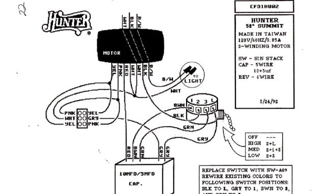
Hunter Ceiling Fan Capacitor – Two why you should install a ceiling fan, heating and cooling. If you live in the cold climate, fans can push heated air gathered at the ceiling down again. Ceiling fans might be simple to install for those who have some mechanical aptitude. Current ceiling fans have remote-controls to vary speed and adjust lighting. If your room already includes a permanent fixture inside ceiling, your permanent fixture probably has one hot or feed wire gonna it, the neutral white and also the bonding green or copper. Essentially this is a three-wire system. Many new construction homes have four wires available, one for your light and one for your fan motor control and also the neutral and ground. If you simply have one Hot wire feeding the ceiling junction box, the remote-control fans work together with your application. Additionally some remote-controlled fans use wall controller which sends its signal on the fan like a TV remote. It just looks like a wall control unit. If you merely have the power wire for the remote-controlled fan, please cap over fourth wire which you will not need to use. This must be shown in your directions that had the fan assembly.
Once you’ve acquired a lover that suits you, build it according on the instructions given. Some fans can be a bit more complex, ask a buddy to assist if you need to. It is best to make sure it is assembled correctly, using a ceiling fan blade thud yourself the top might be annoying. Once you’ve the pre-assembly completed, now you can prepare the ceiling junction box. Of course I know you’ve already made sure the power on the ceiling box is powered down with no one can energize it accidentally. Once you’ve succeeded in doing so, you should find three wires inside J-box. A copper or green wire for bonding. A white wire for your neutral as well as a red or black wire for your power. If your junction box includes a fourth wire, this would be set up for a wall controlled fan switch that is great and allows you to use a non-remote wall controller. I should mention that some all fans have a wall controllers designed as remotes so don’t be confused as these all assist the singular feed in your ceiling junction box.
A word about weight, not yours but anything concerning the sized your fan. If you’ve a sizable fan and its weighted near 12 pounds or even more, you might need a special junction box that could keep the more weight. I would recommend you may well ask someone who knows about these heavier fans you might need what you will be gonna install. Most fans are lighter and might be positioned in most junction boxes without modifications.
Now let’s get it up there, the fan that is certainly. Many fans have a Hanger the same shape as a U. Install this hanger on your box, the screws must be 8/32 types. That means a size 8 diameter or gauge screw with 32 threads per inch. Once you’ve the hanger installed, pick-up your fan motor devoid of the blades installed and it for the hanger. This allows you the electrician to get together the wires without struggling to juggle the motor and wire it as well. Connect the bonding wire on the chassis as noted inside instructions. Next connect the white neutral wire, and after this the black wire. Swing the fan into place while using parts provided. Some have brackets, some utilize a metal plate while others use preformed mounting bases. Use your instructions and you will have a lover right away. Smaller fans may need one to pre-assemble your blades before hanging the fan. I always found installing the motor first and then installing the blades last is easier. It does require however, one to work above your head to find the blades attached.
Once you’ve the fan hanging, the blades installed and everything tightened now you can step over ladder, breathe deeply, then install the wall controller as provided. These all vary in design nevertheless they all follow similar procedures. Remember, you will find a line and load situation here. This means, the queue side could be the pair of wires the feed to the switch box from your panel even though the Load side is gonna your fan. This is critical so be sure to view the difference. Connect the Load side first: Connect your bonding wire first. Then connect your white neutral wire. Then your hot wire. Next perform the Line (incoming) side next: Bond or ground should already be composed on the new controller. Next wire your white neutral on the controllers neutral for your Line side. You may have already wired your neutrals together in accordance with your instructions. Now wire your Hot or Power wire on the Line side of the controller. If you’ve the fourth wire in that room, cap them back or use it for your motor control and connect it accordingly for your directions. Red to Red is truly the case here. Once completed, make yourself some Iced Tea and get your fan.
